- 您现在的位置:买卖IC网 > Sheet目录341 > MAX7302ATE+ (Maxim Integrated)IC LED DRIVER LINEAR 16-TQFN
SMBus/I 2 C Interfaced 9-Port,
Level-Translating GPIO and LED Driver with CLA
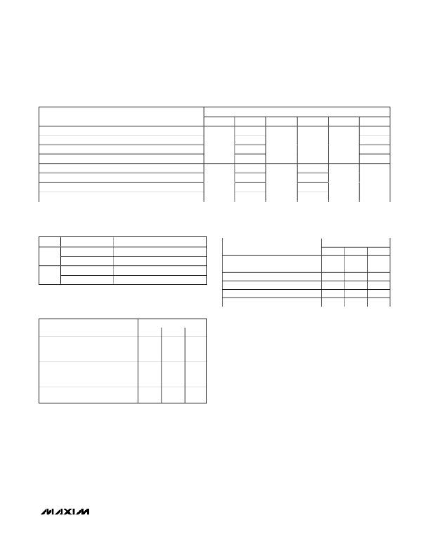
Table 14. CLA1 (P6–P9) Configuration Register Setting (0x29) (continued)
FUNCTION
D5
D4
REGISTER BIT
D3 D2
D1
D0
2 input AND/OR P6 and P8 noninverted
0
0
2 input AND/OR P6 and P8 inverted
2 input AND/OR P6 inverted and P8
1
1
0
0
X
1
0
1
2 input AND/OR P6 and P8 both inverted
2 input AND/OR P7 and P8 noninverted
1
0
0
1
2 input AND/OR P7 and P8 inverted
2 input AND/OR P7 inverted and P8
1
0
1
1
1
0
0
X
2 input AND/OR P7 and P8 both inverted
1
1
Table 15. Output P9 and Cascade P5
Input Configuration
Table 17. Configurable Logic-Array Lock
Register (0x71)
BIT
D7
D6
LOGIC LEVEL
0
1
0
1
FUNCTION
Cascade input noninverted
Cascade input inverted
Output noninverted
Output inverted
REGISTER
CLA0 and CLA1 configurable
logic lock
CLA0 is not locked
CLA0 is locked
CLA1 is not locked
REGISTER DATA
D7–D2 D1 D0
CLA1 CLA0
— X 0
— X 1
—
0
X
Table 16. Configurable Logic-Array
CLA1 is locked
—
1
X
Enable Register (0x70)
REGISTER
REGISTER DATA
D7–D2 D1 D0
CLA0 and CLA1 configurable
logic enable
CLA1
CLA0
Ports P2–P5 are GPIO ports
Ports P2–P5 are configurable logic
CLA0
Ports P6–P9 are GPIO ports
Ports P6–P9 are configurable logic
CLA1
—
—
—
—
X
X
0
1
0
1
X
X
______________________________________________________________________________________
19
发布紧急采购,3分钟左右您将得到回复。
相关PDF资料
MAX7307AUB+T
IC LED DRIVER LINEAR 10-UMAX
MAX831EVKIT-SO
EVAL KIT FOR MAX831
MAX8513EVKIT
EVAL KIT FOR MAX8513
MAX8552EUB+
IC DRIVER MOSFET HS 10-UMAX
MAX8595XETA+T
IC LED DRIVR WHITE BCKLGT 8-TDFN
MAX8607ETD+T
IC LED DRIVR PHOTO FLASH 14-TDFN
MAX8608YETD+T
IC LED DRVR WT/OLED BCKLT 14TDFN
MAX8631XETI+T
IC LED DRVR WHITE BCKLGT 28-TQFN
相关代理商/技术参数
MAX7302ATE+T
功能描述:外围驱动器与原件 - PCI 9-Port Level-Trans GPIO & LED Driver RoHS:否 制造商:PLX Technology 工作电源电压: 最大工作温度: 安装风格:SMD/SMT 封装 / 箱体:FCBGA-1156 封装:Tray
MAX7302EVKIT+
制造商:Maxim Integrated Products 功能描述:MAX7302 EVAL KIT - Boxed Product (Development Kits)
MAX7304
制造商:MAXIM 制造商全称:Maxim Integrated Products 功能描述:I2C-Interfaced 16-Port, Level-Translating GPIO and LED Driver with High Level of Integrated
MAX7304_12
制造商:MAXIM 制造商全称:Maxim Integrated Products 功能描述:I2C-Interfaced 16-Port,Level-Translating GPIO and LED Driver
MAX7304ATG+
制造商:Maxim Integrated Products 功能描述:IC-INTERFACED 16-PORT, LEVEL-TRANSLATING GPIO AND LED DRIVER - Rail/Tube 制造商:Maxim Integrated Products 功能描述:IC LED DRVR LINEAR 24TQFN
MAX7304ATG+T
制造商:Maxim Integrated Products 功能描述:IC-INTERFACED 16-PORT, LEVEL-TRANSLATING GPIO AND LED DRIVER - Tape and Reel 制造商:Maxim Integrated Products 功能描述:IC LED DRVR LINEAR 24TQFN
MAX7304AWA+T
功能描述:LED照明驱动器 I2C Interfaced 16-Port Lvl-Translator GPIO & LED Driver w. Hi Lvl Integrated ESD Protect. RoHS:否 制造商:Maxim Integrated 输入电压: 工作频率: 最大电源电流: 输出电流: 最大工作温度: 安装风格: 封装 / 箱体:
MAX7304ETG+
功能描述:接口-I/O扩展器 I2C 16Port LT GPIO and LED Driver RoHS:否 制造商:NXP Semiconductors 逻辑系列: 输入/输出端数量: 最大工作频率:100 kHz 工作电源电压:1.65 V to 5.5 V 工作温度范围:- 40 C to + 85 C 安装风格:SMD/SMT 封装 / 箱体:HVQFN-16 封装:Reel
